
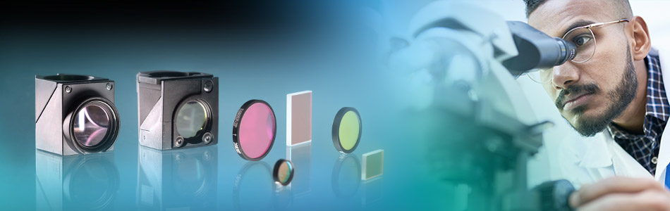
Optical Filters
High Spectral Performance and Versatile in Use
Optical filters play a key role in many biophysical measurement applications, like fluorescence microscopy and Raman spectroscopy, including super-resolution techniques. For these applications, we offer in collaboration with prestigious filter manufacturers a comprehensive portfolio as well as customized solutions. Besides an in-depth and expert consultation service, we can provide you with filter components for personal testing. Working closely with research-institutes and industry, we continuously optimize filter designs – an effort that has produced lasting collaborations with OEM partners.
Select Optical Filter by Application
Select Optical Filter by Type / Specification
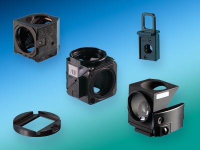
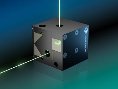
Customized Filter Designs, Accessories and Polar Guard Module
Useful Information About Optical Filters – If You Want to Know More
What Are Optical Filters?
Optical filters are used to control or filter the light depending on its wavelength (color). Depending on its wavelength, the light can be transmitted, absorbed (swallowed) or reflected. For example, the aim can be to transmit blue light and reflect/absorb red light. Optical filters differ roughly in the way they work in that there are colored glasses and interference filters (dielectric-coated glasses). Both types have different advantages and disadvantages, as their mode of operation is different.
How Do Optical Filters Work?
Colour Optical Glass
In the case of coloured glass, the material (glass) is doped so that, depending on the wavelength, the light is transmitted or absorbed. The doping can be varied and adjusted so that the spectral properties (light colour) of the filter result in a long pass filter, short pass filter, band pass filter, multiband filter or neutral filter. The absorbed light is converted into heat and is no longer available in the system as light. This can be helpful to reduce unused ( disturbing ) light and thus improve the quality (contrast) of the result. The surface quality (wedge defects, flatness) of the filter can also be improved afterwards by mechanical methods. A significant disadvantage of colored glasses, however, is that their spectral properties cannot be produced " in any form" and are therefore not sufficient for typical applications in fluorescence microscopy and laser physics. On the other hand, a common area of application is photography and protective glasses for hazardous light sources.
Optical Interference Filters
Interference filters use, as the name suggests, the physical phenomenon of interference. Interference can be found in all oscillations/waves (light, water, sound, etc.), whereby they can mutually amplify or attenuate each other (if they meet in a suitable way). And this effect is used to transmit or reflect defined wavelengths in optical filters. The waves can be made to interfere with each other by letting them transmitting/reflecting at layers of different thickness of different materials. These layers are applied very thinly (in the nanometer range) to a carrier substrate (glass). This means that a part of the light passes through the first layer and a part is reflected. The transmitted part is in turn transmitted and reflected at the following boundary layer (2nd layer). The two reflected parts from different reflective layers meet again on the "return path" and can therefore interfere with each other. This results in wavelengths that are only transmitted and others that are only reflected.

What is sketched here as an example with one layer is, in the case of complex (steep-edged) filters, hundreds of layers of different materials, which are reproducibly applied homogeneously and evenly to a carrier material.
You can find more on this topic in the presentation by Turan Erdogan, IDEX/Semrock:
» Construction of Optical Filters (PDF)
In the fields of microscopy and laser physics today, interference filters are used almost exclusively, since the spectral properties are much more defined and can be implemented more extremely. If the transmitted and reflected light is to be used further, beam splitters are used. These differ from optical interference filters in that they are typically installed at 45 degrees (instead of below 0 degrees).

Properties of Optical Filters
Transmission And Blocking of Optical Filters
Important properties of optical filters are their spectral characteristics. Wavelength dependent transmission and blocking is the main feature. The transmission of optical filters is given in % and in the best case it is close to 100%. The blocking of optical filters is given in OD (optical density) and is a logarithmic scale. OD0 corresponds to a blocking of 0 or a transmission of 100% - a blocking of OD1 corresponds to a transmission of 10% - OD2 / 1% - OD3 / 0.1% etc.
For interference filters a blocking of measured OD6 is now common, which corresponds to a transmission of 0.0001%. Designed blockings can be much higher - but it is difficult to measure them accurately. Such high contrasts (nearly 100% transmission and blocking with OD6) are not nearly achievable with colored glasses (for close spectral points), so they are not suitable for fluorescence microscopy.
Important note: The parallel arrangement of optical interference filters increases blocking only marginally, since the light that is not transmitted is reflected and not absorbed.
You can find more on this topic in the presentation by Turan Erdogan, IDEX/Semrock: » Coherence and Combining Filters (PDF)
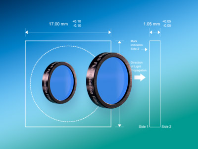
Angle of Incident Light
The 'CHA' (cone half angle) and 'AOI' (angle of incidence) influence the transmitted spectrum of optical interference filters. The layer thickness on the substrate depends on the incident wavelength. If the angle of the incident light changes, the path of the light through the applied layer also changes relatively to this - and thus the spectral properties of the optical filter.
In short, the transmitted spectrum of the filter shifts to short wavelengths if the angle of incidence of the optical filters differs from 0 degrees. For small angles (up to 5 degrees), this is not critical and can be compensated by the layer design. In the case of the tunable optical filters, this effect is in fact used to make the spectral properties of the optical filter tuneable. This effect does not occur with the color glass optical filters due to the principle of operation.


What Kind of Optical Filters Are Available?
Optical Short Pass Filters
Optical short pass filters transmit the light in the short wavelength range and block the light in the long wavelength range. A cut-off wavelength defines the edge and depending on the quality and complexity of the filter, this edge has a different steepness. The more layers are applied, the faster the edge falls off and, depending on the application, more valuable light can be used.


As an example we use the 532nm short pass filter » 532 SP Edge Basic (Art. No. F76-535). In the illustration of the transmission of the optical short pass filter the edge at 532nm in connection with the transmission in the short wavelength range and the wide blocking up to 1200nm is clearly visible.
When looking at the edge in the blocking diagram, it becomes obvious how steep the edge falls. Within 3-4 nm a blocking of six orders of magnitude from OD0.1 to OD6 is achieved.
A list of optical short pass filters from AHF can be found here:
Optical Long Pass Filters
Optical long pass filters are inverse to optical short pass filters. In other words, they transmit the light in the long-wave spectrum and block the short-wave spectrum. There is also a cut-off wavelength that separates the transmission range from the blocking. As an example we use the long pass filter » 473 LP Edge Basic (Art. No. F76-472).
The optical long pass filters at AHF can be found here:
Optical Bandpass Filters
Optical bandpass filters are a combination of a short pass filter and a long pass filter. The result is a band that transmits light in a specific spectral range and reflects it otherwise.
The » bandpass filter 525/50 (Art. No. F37-516) serves as an example:
This optical bandpass filter transmits the light around the central wavelength of 525nm with a bandwidth of 50nm. Outside the band the optical filter blocks the remaining wavelengths: Consequently, a band is 'cut' out of the spectrum which can be used further.
Optical bandpass filters at AHF can be found here:
Optical Multiband Filters
Not only one band can be realized with an optical bandpass filter. There are also dual band (two bands), triple band (three bands), quad band (four bands) and pentaband (five bands) optical filters.
The optical » pentaband filter (Art. No. F72-855) with the central wavelengths at 440nm, 521nm, 607nm, 694nm and 809nm serves as an example.
A typical application for optical multiband filters is fluorescence microscopy with the use of multiple dyes.
Optical Notch Filters
An optical notch filter is the inverse of a bandpass filter. Instead of transmitting one band, as with an optical bandpass filter, one band is blocked and the rest of the spectrum is transmitted. So when you look at the blocking of an optical notch filter, it is similar to the transmission of a bandpass filter. Typical applications for Notch Filters can be found in laser physics. In this case a notch filter is used to block the laser light and the remaining light is used. The » 594 nm notch filter (Art. No. F40-593):

Beam Splitters
Optical beam splitters have the special characteristic that they are not designed to be used at an angle of incidence below 0 degrees (as with optical filters) but at an angle of incidence of 45 degrees. They are used to combine or separate two light paths. In fluorescence microscopy, for example, the excitation light is usually directed onto the sample via the beam splitter and the fluorescence signal from the sample is transmitted through the beam splitter to the user.
Spectral Properties of Beam Splitters
Like the optical filters, the beam splitters are also available as long pass, short pass, multiband pass, notch and neutral beam splitters. Bandpass beam splitters with one band are not common. In general, it should be noted that beam splitters can have a high transmission – but do not have a high blocking. The average blocking of beamsplitters is about OD3 (O.1% transmission) and does not match the high blocking of optical filters, which is about OD6 (0.0001% transmission). I.e. beam splitters are used to 'sort' the light but not to block unwanted light. This is what the optical filters are used for.

Flatness of Beam Splitters
The coating on the substrate can cause tension which bends the beam splitter. This is more or less critical depending on the application. In the classical epi-fluorescence application (in combination with lamps) the image of the sample is transmitted through the beam splitter and therefore has little influence on the image quality. Here the use of standard beam splitters is sufficient. The situation becomes more critical when lasers are used and the steel quality should not be influenced. If the laser is directed onto the sample via the beam splitter, a beam splitter with increased flatness should be used. There are special laser beam splitters for this purpose, which are significantly flatter than the standard beam splitters due to their design.
The flatness of the beam splitter is most critical when the whole image of the sample is reflected by the beam splitter. This is when the Imaging beam splitters are used. These are designed for this purpose and have an exceptional flatness. In general, it should be noted that the information on flatness from different manufacturers is not uniform and therefore not directly comparable. Please contact us, we will be pleased to advise you!
Measuring the Flatness
Furthermore, we are able to measure the flatness of beam splitters with high precision. This enables us to check the manufacturer's specifications on the one hand, and we can also measure your beam splitter if you want to know how flat it is.
For more information on the flatness of beamsplitters, please contact Turan Erdogan, IDEX/Semrock: Optical Filters: Flatness (PDF)
You can find beam splitters at AHF here:
Optical Laser Bandpass Filters
A special feature of the bandpass filters are optical filters for laser applications. Lasers have the characteristic to have a very defined and very narrow wavelength. And an optical filter that transmits exactly this wavelength and reflects the rest requires a very narrow optical filter – ideally in the sub-nanometer range.

The optical » sub-nanometer bandpass filter 589.5/1 (Art. No. F97-589) serves as an example.
The difficulty with this filter is the very narrow band and the wide blocking. The suppression of the higher harmonics of the transmission band is complex and requires a very complex filter design.
Fluorescence Filters
In fluorescence microscopy, optical filters are needed to clean the excitation and emission beams. These are usually dielectrically coated interference filters. First of all, the excitation filter spectrally filters the mostly white light of the excitation lamp in such a way that only that part of the light passes through which can be excited by the fluorescence markers. For example, the green fluorescent protein GFP is excited in the blue range. Due to the Stokes shift, the emission light of the fluorescent marker does a shift to the longer wavelength part of the spectrum.
The collected fluorescence light is then separated from the remaining, scattered excitation light by the emission filter. It is important to avoid any spectral overlap of the excitation filter and emission filter, otherwise a so-called 'bleed-through' of the excitation light – which is very strong compared to the emission light – will occur and destroy the usually excellent contrast of the images. The 'out-of-band blocking (suppression of unwanted wavelengths) is particularly decisive in this respect. For this reason, AHF analysentechnik only provides optical high-end filters that guarantee blocking from OD6 to OD8 in the relevant spectral ranges. Only this way, the fluorescence light can be measured virtually against a completely black background and makes individual molecules visible in a sufficient darkened room – even with the eye.
Transmission of the filters is another critical point. Only when these come close to the theoretical limit of >95%, shortest exposure times can be selected, which spares the markers because less light is needed for detection.